Create a realistic model
Although this should be very straightforward, and while the 3D view in Altium is very accurate, getting it out of there is an entirely different story.
Step 1
This is, as you’d expect to export a STEP file from Altium.
Use File > Export > STEP 3D
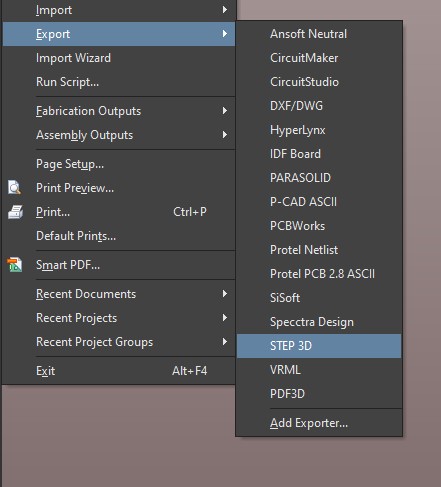
Remember to export all 3D bodies as well. But you get no traces, silkscreen or pads in a STEP file.
So on to the next step.
Step 2
Open the STEP file in Fusion 360 (or Keyshot - the process is similar)
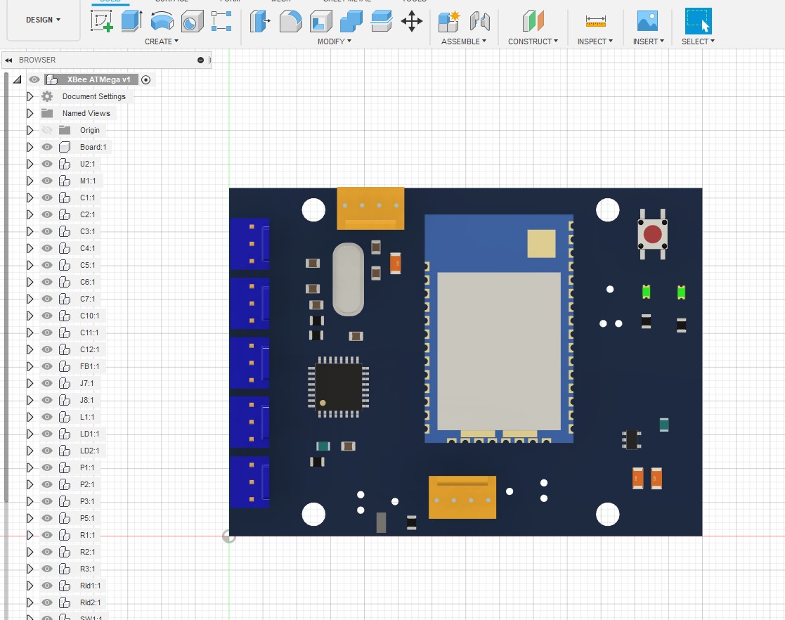
Make sure the main solids are free from errors, and there’s no z-fighting.
Step 3
In Altium, open Page Setup and Print Properties.
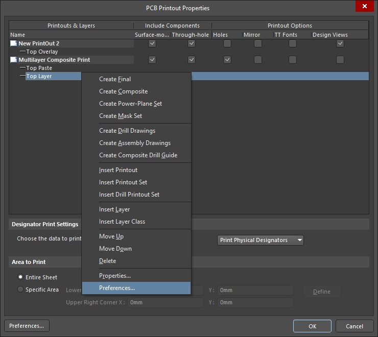
Right click any item and select Preferences
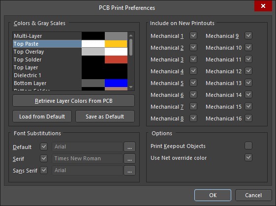
- Set the Top Paste layer colour to gold, tin
- Set the Top Overlay colour to white
- Set the Top Solder colour to black or a darker colour
Remove the other layers, and set up a composite image in this order:
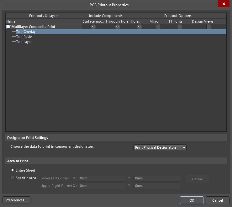
Print as a PDF. Convert to PNG or TIF.
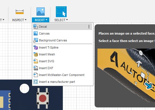
Step 4
Import the image into Fusion 360 as a decal:
Select the top face. Make sure Chain Faces is unchecked.
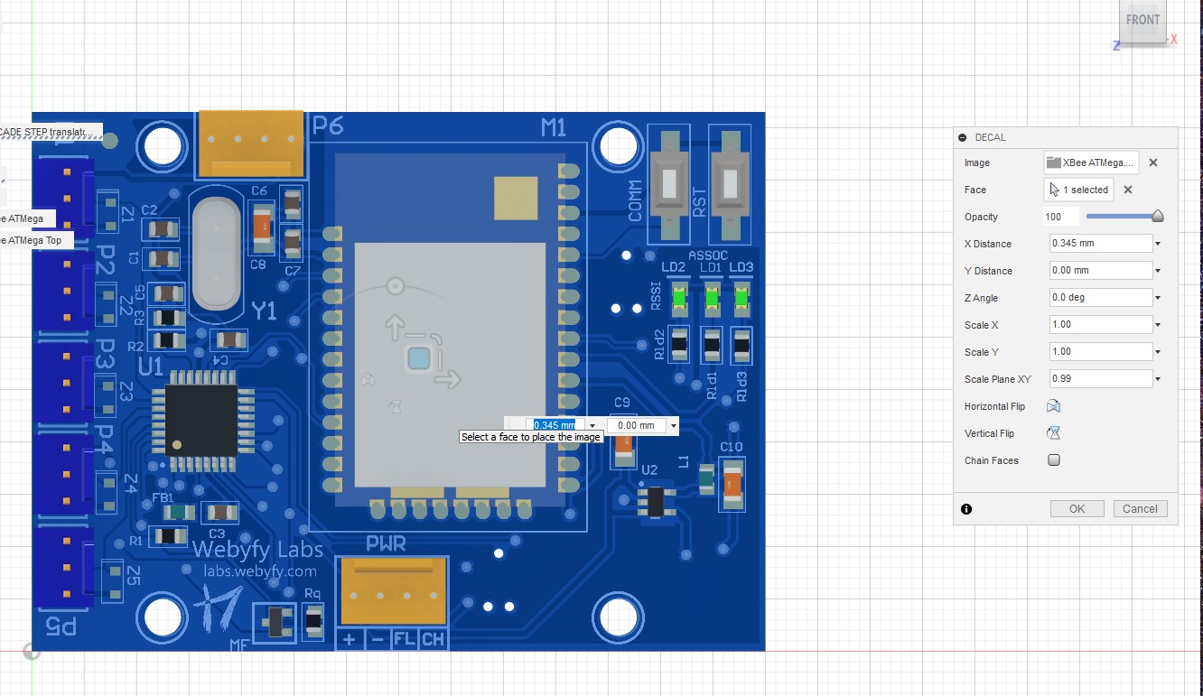
Move the decal into position.
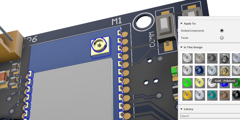
Step 5
Open the Appearance tab, and map more accurate to the existing materials.
You can do this by selecting a material, selecting all instances of it, and dragging a new material.
Here I’m adding a polished gold material for the castellations.
Now set up some soft lighting , a solid environment color, and hit Render!
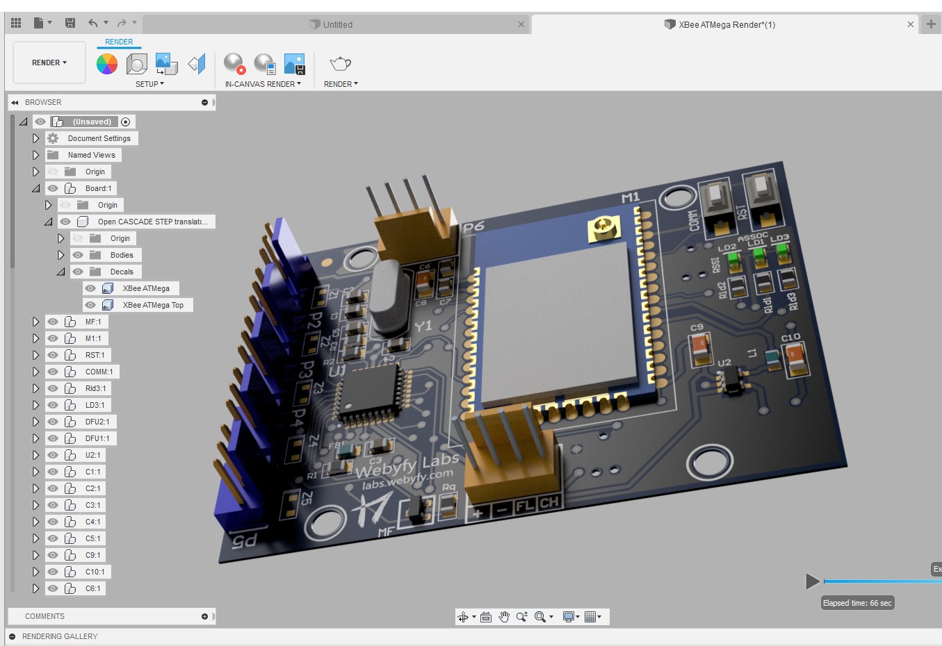
And you should have something like this.
Last modified on 2019-02-19
Comments Disabled.